Micro
- arduino
- Как настроить семисегментный дисплей на arduino
- Как взаимодествовать с OLED дисплеем через ESP32?
- Энкодер
- Esp
- Обзор микроконтроллера ESP8266
- Как взаимодействовать с OLED дисплеем с помощью ESP32? ESP32 OLED Display инструкция
- mqtt
- raspberry
arduino
Как настроить семисегментный дисплей на arduino
Семисегментный дисплей часто используется для домашнего применения например в микроволновых печах, машинах для стирки и воздушных кондиционерах. Они достаточно просты и эффективны для отображения цифровой информации. В этой инструкции разберем как подключить и запрограммировать дисплей с одним или несколькими цифрами на базе ардуино.
Семи сегментный дисплей имеет больше разнообразие размеров и цветов. Красный, голубой и зеленый самые распространненный и их легко найти. Размеры могут варьироваться от 0.56 дюймов до 4 и даже 6.5. Некоторые имеют одну цифру, другие две или даже четыре.
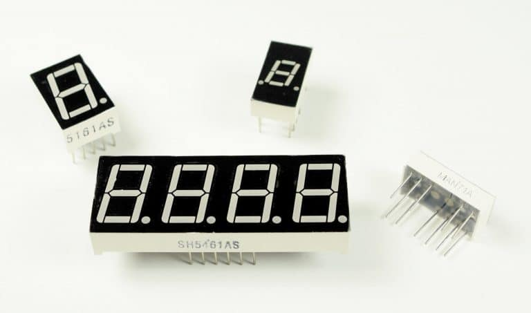
Ардуино 7 сегментный дисплей - одна цирфра и 4 цифры. Прежде чем преступим работать с 7 сегментным дисплеем, нужно понять: базовые вещи для LED и как с ними управляться.
The 3-in-1 Smart Car and IOT Learning Kit from SunFounder has everything you need to learn how to master the Arduino. It includes all of the parts, wiring diagrams, code, and step-by-step instructions for 58 different robotics and internet of things projects that are super fun to build!
LED основы
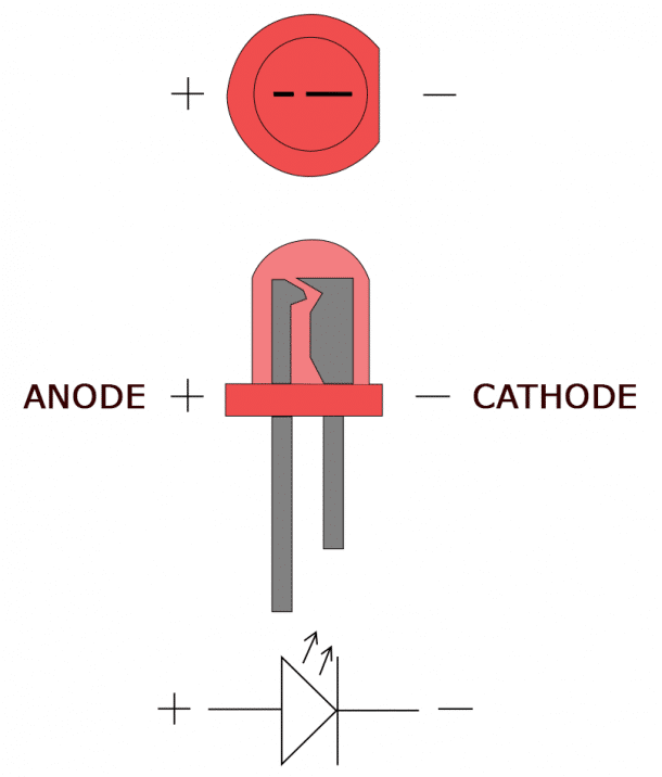
Простой LED состоит из 2х частей: анод и катод. Анод позитивный конец, ктод - негативный
Arduino 7 Segment Display Tutorial - LED Anode and Cathode
To power the LED, you connect the cathode to ground and the anode to the voltage supply. The LED can be turned on or off by switching power at the anode or the cathode.
ANODE TO GPIO
With the LED’s anode connected to a digital pin, the cathode is connected to ground:
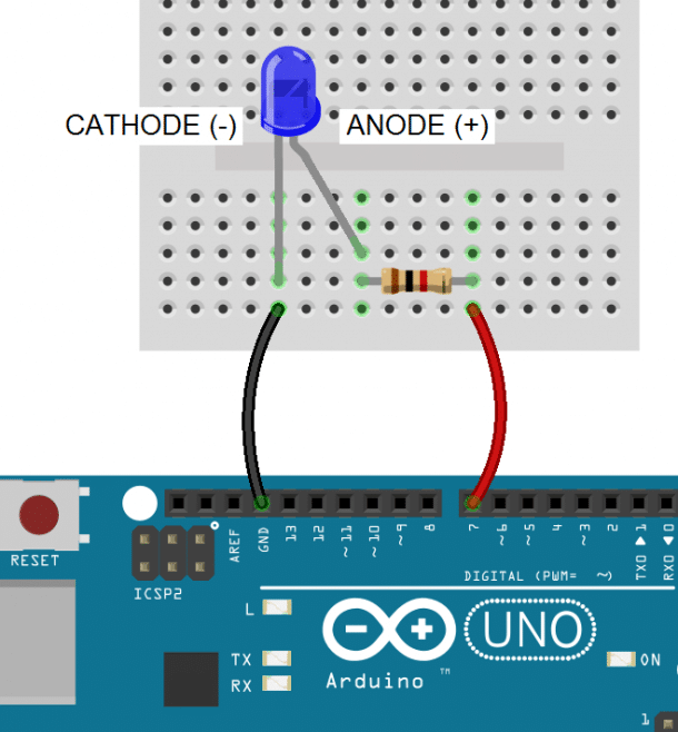 Arduino 7 Segment Display Tutorial - Anode to GPIO
Note: All LEDs need a current limiting resistor placed on either the anode side or cathode side to prevent the LED from burning out. The resistor value will determine how bright the LED shines. 1K ohms is a good place to start, but you can calculate the ideal value with an LED resistor calculator.
Arduino 7 Segment Display Tutorial - Anode to GPIO
Note: All LEDs need a current limiting resistor placed on either the anode side or cathode side to prevent the LED from burning out. The resistor value will determine how bright the LED shines. 1K ohms is a good place to start, but you can calculate the ideal value with an LED resistor calculator.
To light up an LED with the anode connected to a digital pin, you set the digital pin to HIGH:
void setup(){
pinMode(7, OUTPUT);
digitalWrite(7, HIGH);
}
void loop(){
}
In the void setup() block, we configure GPIO pin 7 as an output with pinMode(7, OUTPUT) and drive it high with digitalWrite(7, HIGH).
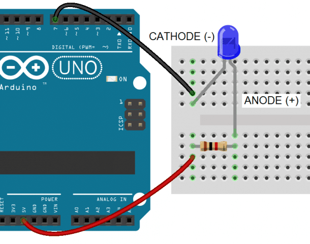
CATHODE TO GPIO
With an LED’s cathode connected to a digital pin, the anode is connected to Vcc. To turn on the LED, the digital pin is switched LOW, which completes the circuit to ground:
Arduino 7-Segment Display Tutorial - Cathode to GPIO In this case we drive GPIO pin 7 LOW with digitalWrite(7, LOW). This closes the circuit and allows current to flow from Vcc to ground:
void setup(){
pinMode(7, OUTPUT);
digitalWrite(7, LOW);
}
void loop(){
}
HOW 7-SEGMENT DISPLAYS WORK
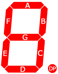
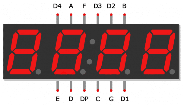
Seven segment displays consist of 7 LEDs, called segments, arranged in the shape of an “8”. Most 7-segment displays actually have 8 segments, with a dot on the right side of the digit that serves as a decimal point. Each segment is named with a letter A to G, and DP for the decimal point:
 Each segment on the display can be controlled individually, just like a regular LED.
There are two types of 7-segment displays – common cathode and common anode.
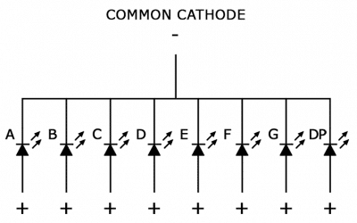
COMMON CATHODE DISPLAYS
In common cathode displays, all of the cathodes are connected to ground and individual segments are turned on and off by switching power to the anodes:
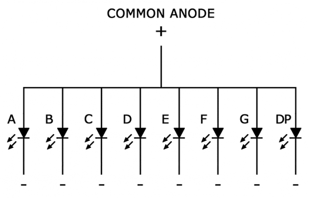
COMMON ANODE DISPLAYS
In common anode displays, all of the anodes are connected to Vcc, and individual segments are turned on and off by switching power to the cathodes:
CONNECTING 7-SEGMENT DISPLAYS TO THE ARDUINO
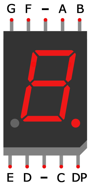
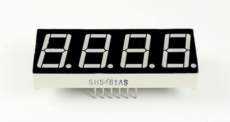
Single digit seven segment displays typically have 10 pins. Two pins connect to ground, and the other 8 connect to each of the segments. Here is a pin diagram of the popular 5161AS common cathode display:
 Before you can connect your display to the Arduino, you need to know if it’s common anode or common cathode, and which pins connect to each segment. This information should be in the datasheet, but if you can’t find the datasheet or you don’t know your display’s part number, I’ll show you how to figure this out below…
HOW TO TELL IF YOU HAVE A COMMON ANODE OR COMMON CATHODE DISPLAY
To determine if a display is common anode or common cathode, you can probe the pins with a test circuit constructed like this:
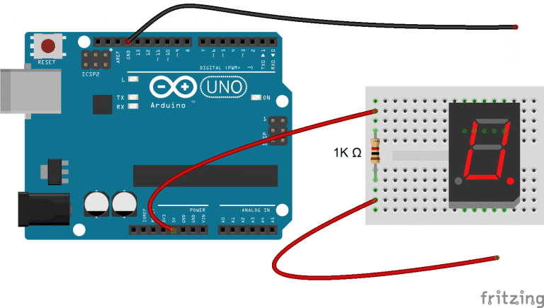 Connect the ground (black) wire to any pin of the display. Then insert the positive (red) wire into each one of the other pins. If no segments light up, move the ground wire over to another pin and repeat the process. Do this until at least one segment lights up.
When the first segment lights up, leave the ground wire where it is, and connect the positive wire to each one of the other pins again. If a different segment lights up with each different pin, you have a common cathode display. The pin that’s connected to the ground wire is one of the common pins. There should be two of these.
If two different pins light up the same segment, you have a common anode display. The pin that’s connected to the positive wire is one of the common pins. Now if you connect the ground wire to each one of the other pins, you should see that a different segment lights up with each different pin.
HOW TO DETERMINE THE PINOUT FOR YOUR DISPLAY
Now draw a diagram showing the pins on your display. With the common pin connected to the ground wire (common cathode) or positive wire (common anode), probe each pin with the other wire. When a segment lights up, write down the segment name (A-G, or DP) next to the corresponding pin on your diagram.
CONNECTING SINGLE DIGIT DISPLAYS TO THE ARDUINO
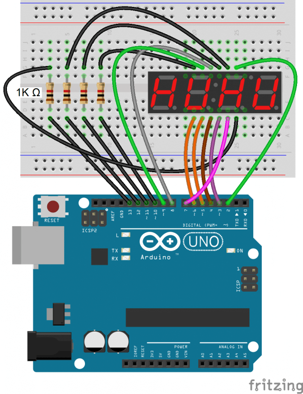
Once you have the pin layout figured out, connecting the display to an Arduino is pretty easy. This diagram shows how to connect a single digit 5161AS display (notice the 1K ohm current limiting resistor connected in series with the common pins):
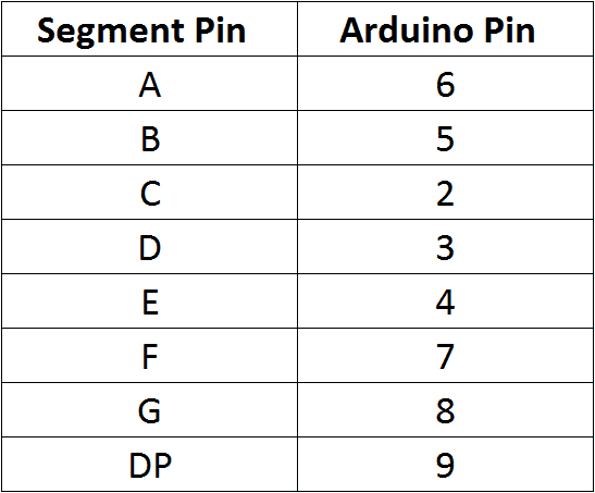
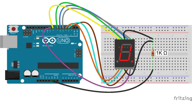 In the example programs below, the segment pins connect to the Arduino according to this table:
PROGRAMMING SINGLE DIGIT DISPLAYS
INSTALL THE LIBRARY
We’ll use a library called SevSeg to control the display. The SevSeg library works with single digit and multi-digit seven segment displays. You can download the library’s ZIP file from GitHub or download it here:
Circuit Basics ZIP Icon SevSeg.zip
To install it, open the Arduino IDE, go to Sketch > Include Library > Add .ZIP Library, then select the SevSeg ZIP file that you downloaded.
PRINTING NUMBERS TO THE DISPLAY
This program will print the number “4” to a single digit 7-segment display:
#include "SevSeg.h"
SevSeg sevseg;
void setup(){
byte numDigits = 1;
byte digitPins[] = {};
byte segmentPins[] = {6, 5, 2, 3, 4, 7, 8, 9};
bool resistorsOnSegments = true;
byte hardwareConfig = COMMON_CATHODE;
sevseg.begin(hardwareConfig, numDigits, digitPins, segmentPins, resistorsOnSegments);
sevseg.setBrightness(90);
}
void loop(){
sevseg.setNumber(4);
sevseg.refreshDisplay();
}
In this program, we create a sevseg object on line 2. To use additional displays, you can create another object and call the relevant functions for that object. The display is initialized with the sevseg.begin() function on line 11. The other functions are explained below:
hardwareConfig = COMMON_CATHODE – This sets the type of display. I’m using a common cathode, but if you’re using a common anode then use COMMON_ANODE instead.
byte numDigits = 1 – This sets the number of digits on your display. I’m using a single digit display, so I set it to 1. If you’re using a 4 digit display, set this to 4.
byte digitPins[] = {} – Creates an array that defines the ground pins when using a 4 digit or multi-digit display. Leave it empty if you have a single digit display. For example, if you have a 4 digit display and want to use Arduino pins 10, 11, 12, and 13 as the digit ground pins, you would use this: byte digitPins[] = {10, 11, 12, 13}. See the 4 digit display example below for more info.
byte segmentPins[] = {6, 5, 2, 3, 4, 7, 8, 9} – This declares an array that defines which Arduino pins are connected to each segment of the display. The order is alphabetical (A, B, C, D, E, F, G, DP where DP is the decimal point). So in this case, Arduino pin 6 connects to segment A, pin 5 connects to segment B, pin 2 connects to segment C, and so on.
resistorsOnSegments = true – This needs to be set to true if your current limiting resistors are in series with the segment pins. If the resistors are in series with the digit pins, set this to false. Set this to true when using multi-digit displays.
sevseg.setBrightness(90) – This function sets the brightness of the display. It can be adjusted from 0 to 100.
sevseg.setNumber() – This function prints the number to the display. For example, sevseg.setNumber(4) will print the number “4” to the display. You can also print numbers with decimal points. For example, to print the number “4.999”, you would use sevseg.setNumber(4999, 3). The second parameter (the 3) defines where the decimal point is located. In this case it’s 3 digits from the right most digit. On a single digit display, setting the second parameter to “0” turns on the decimal point, while setting it to “1” turns it off.
sevseg.refreshDisplay() – This function is required at the end of the loop section to continue displaying the number.
COUNT UP TIMER
This simple program will count up from zero to 9 and then loop back to the start:
#include "SevSeg.h"
SevSeg sevseg;
void setup(){
byte numDigits = 1;
byte digitPins[] = {};
byte segmentPins[] = {6, 5, 2, 3, 4, 7, 8, 9};
bool resistorsOnSegments = true;
byte hardwareConfig = COMMON_CATHODE;
sevseg.begin(hardwareConfig, numDigits, digitPins, segmentPins, resistorsOnSegments);
sevseg.setBrightness(90);
}
void loop(){
for(int i = 0; i < 10; i++){
sevseg.setNumber(i, i%2);
delay(1000);
sevseg.refreshDisplay();
}
}
The code is similar to the previous sketch. The only difference is that we create a count variable “i” in the for statement on line 16 and increment it one number at a time.
The sevseg.setNumber(i, i%2) function prints the value of i. The i%2 argument divides i by 2 and returns the remainder, which causes the decimal point to turn on every other number.
The count up timer is a nice way to demonstrate the basics of how to program the display, but now let’s try to make something more interesting.
ROLLING DICE
This example consists of a push button and a single 7 segment display. Every time the push button is pressed and held, the display loops through numbers 0-9 rapidly. Once the button is released, the display continues to loop for a period of time almost equal to the time the button was pressed, and then displays a number along with the decimal point to indicate the new number.
To build the circuit (with the 5161AS display), connect it like this:
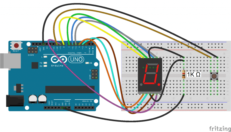 Then upload this program to the Arduino:
#include "SevSeg.h"
SevSeg sevseg;
const int buttonPin = 10; // the pin that the pushbutton is attached to
int buttonState = 0; // current state of the button
int lastButtonState = LOW; // previous state of the button
int buttonPushCounter = 0; // counter for the number of button presses
long counter = 0;
long max_long_val = 2147483647L;
void setup(){
byte numDigits = 1;
byte digitPins[] = {};
byte segmentPins[] = {6, 5, 2 , 3, 4 , 7, 8, 9};
bool resistorsOnSegments = true;
byte hardwareConfig = COMMON_CATHODE;
sevseg.begin(hardwareConfig, numDigits, digitPins, segmentPins, resistorsOnSegments);
sevseg.setBrightness(90);
pinMode(buttonPin, INPUT_PULLUP);
Serial.begin(9600);
lastButtonState = LOW;
}
void loop(){
buttonState = digitalRead(buttonPin);
if(buttonState == HIGH){
buttonState = LOW;
}
else
buttonState = HIGH;
if(buttonState == HIGH){
Serial.println("on");
lastButtonState = HIGH;
buttonPushCounter++;
if(counter < max_long_val)
counter++;
buttonPushCounter %= 9;
sevseg.setNumber(buttonPushCounter, 1);
sevseg.refreshDisplay();
delay(100 - (counter%99));
}
else{
Serial.println("off");
if(lastButtonState == HIGH){
Serial.println("in");
buttonPushCounter++;
buttonPushCounter %= 7;
if(buttonPushCounter == 0)
buttonPushCounter = 1;
counter--;
sevseg.setNumber(buttonPushCounter, 1);
sevseg.refreshDisplay();
delay(100 - (counter%99));
if(counter == 0){
lastButtonState = LOW;
sevseg.setNumber(buttonPushCounter, 0);
sevseg.refreshDisplay();
}
}
}
}
4 DIGIT 7-SEGMENT DISPLAYS
So far we have only worked with single digit 7-segment displays. To display information such as the time or temperature, you will want to use a 2 or 4 digit display, or connect multiple single digit displays side by side.
 In multi-digit displays, one segment pin (A, B, C, D, E, F, G, and DP) controls the same segment on all of the digits. Multi-digit displays also have separate common pins for each digit – these are the digit pins. You can turn a digit on or off by switching the digit pin.
 I’m using a 4 digit 7-segment display with the model number 5641AH, but the wiring diagrams below will also work with the 5461AS.
Here is a diagram showing the pinout of these displays:
 The digit pins D1, D2, D3 and D4 need to be connected to current limiting resistors, since they are the common terminals of the digits. The connections are shown below:
 This simple program will print the number “4.999” to the display:
#include "SevSeg.h"
SevSeg sevseg;
void setup(){
byte numDigits = 4;
byte digitPins[] = {10, 11, 12, 13};
byte segmentPins[] = {9, 2, 3, 5, 6, 8, 7, 4};
bool resistorsOnSegments = true;
bool updateWithDelaysIn = true;
byte hardwareConfig = COMMON_CATHODE;
sevseg.begin(hardwareConfig, numDigits, digitPins, segmentPins, resistorsOnSegments);
sevseg.setBrightness(90);
}
void loop(){
sevseg.setNumber(4999, 3);
sevseg.refreshDisplay();
}
In the code above, we set the number of digits in line 5 with byte numDigits = 4.
Since multi-digit displays use digit pins, we also need to define which Arduino pins will connect to the digit pins. Using byte digitPins[] = {10, 11, 12, 13} on line 6 sets Arduino pin 10 as the first digit pin, Arduino pin 11 to the second digit pin, and so on.
To print numbers with a decimal point, we set the second parameter in sevseg.setNumber(4999, 3) to three, which puts it three decimal places from the right most digit.
DISPLAYING SENSOR DATA
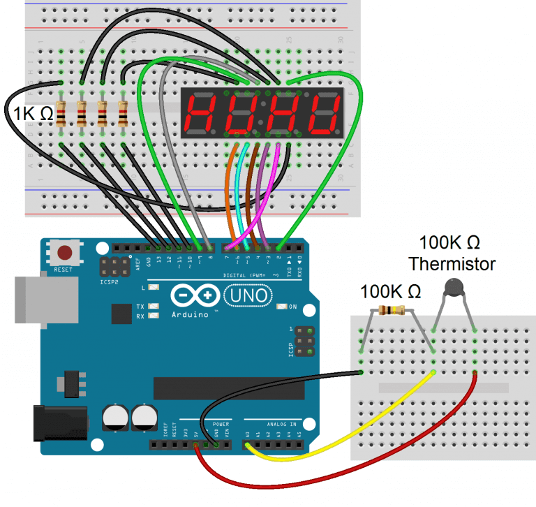
Now let’s read the temperature from a thermistor and display it on a 4 digit display.
Connect the circuit like this:
 If you want to learn more about thermistors, check out our tutorial on using a thermistor with an Arduino.
Once everything is connected, upload this code to the Arduino:
#include "SevSeg.h"
SevSeg sevseg;
int ThermistorPin = 0;
int Vo;
float R1 = 10000;
float logR2, R2, T;
float c1 = 1.009249522e-03, c2 = 2.378405444e-04, c3 = 2.019202697e-07;
void setup() {
byte numDigits = 4;
byte digitPins[] = {10, 11, 12, 13};
byte segmentPins[] = {9, 2, 3, 5, 6, 8, 7, 4};
bool resistorsOnSegments = true;
byte hardwareConfig = COMMON_CATHODE;
sevseg.begin(hardwareConfig, numDigits, digitPins, segmentPins, resistorsOnSegments);
}
void loop() {
Vo = analogRead(ThermistorPin);
R2 = R1 * (1023.0 / (float)Vo - 1.0);
logR2 = log(R2);
T = (1.0 / (c1 + c2 * logR2 + c3 * logR2 * logR2 * logR2));
T = T - 273.15;
T = (T * 9.0) / 5.0 + 32.0; //Comment out for Celsius
static unsigned long timer = millis();
if (millis() >= timer) {
timer += 300;
sevseg.setNumber(T, 2);
}
sevseg.refreshDisplay();
}
This will display the temperature in Fahrenheit on the 7-segment display. To display the temperature in Celsius, comment out line 28.
By itself, the display will update every time the temperature changes even slightly. This creates an annoying flickering. In order to deal with this, we introduce a timer mechanism, where we only read the value from the thermistor every 300 milliseconds (lines 30 to 34).
The temperature variable “T” is printed to the display on line 35 with sevseg.setNumber(T, 2, false).
Как взаимодествовать с OLED дисплеем через ESP32?
В этой инструкции, мы изучим как взаимодействовать с OLED дисплеем через ESP32 плату разработки. Графический OLED дисплей используемый в проекте основан на SSD1306 OLED драйвере IC и взаимодействует через SPI. Его можно испопльзовать для отображения текста, картинки графики и так далее.

Инструкция
OLED или органический светодиод это улучшенная технология, которая исользует пленку с органическим основанием между двумя электродами(анодом и катодом) и когда подается напряжение между электродами, органическая пленка испускает свет.
Главное преимущество OLED дисплея, в том, что она испускает свой собственный свет, и не требует другого источника подсветки. По этой причине OLED дисплеи часто имеют лучший контраст, яркость и углы обзора при сравнении с LCD дисплеями.
Другое важное свойство OLED дисплея это уровень черного цвета. Так как каждый пиксель испускает свой свет в OLED дисплее, чтобы получить черный свет, достаточно отключить пиксель.
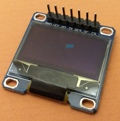
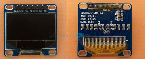
Краткое описание SSD1306 OLED дисплея
Хотите использовать OLED дисплелй в ваших DYI проектах? Хотите отображать важную информацию, вроде IP адреса, Адреса Web сервера? Тогда модуль SSD1306 отличный выбор!

Этот модуль состоит из монохромного OLED дисплея с разрешением 128 на 64 пикселя. Диагональ такого дисплея 0.96. Этот дисплей использует SSD1306 OLED драйвер.
SSD1306 OLED Displays have three types of communication interfaces:
- -bit 6800 Parallel Interface
- 3 or 4 wire SPI
- I2C Of these, the I2C and SPI type OLEDs are very common. It is possible of change the configuration from SPI to I2C and vice-versa (you have solder / de-solder some SMD resistors). The model that I have is using 4-wire SPI Communication.

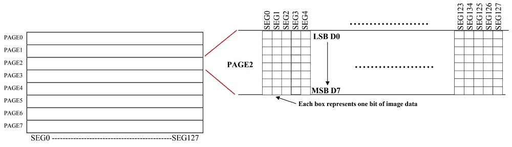
The SSD1306 OLED Driver IC has 128 x 64 bits Graphic Display Data RAM (GDDRAM). It is divided into eight pages (PAGE 0 to PAGE 7) and each page has 128 Segments. Again, each segment consists of 8-bits and each bit represents one pixel of the display.
So, 8 Pages * 128 Segments * 8 Bits = 8192 Bits (1024 Bytes).
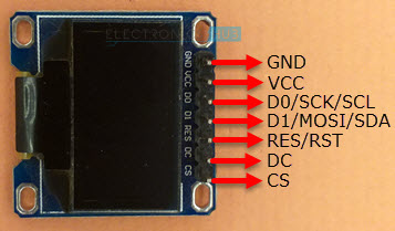
Pinout of OLED Display Module
The following table shows the Pinout of 7-pin SPI based OLED Display Module.
| Pin (Alternative Names) | Description |
|---|---|
| GND | Ground |
| VCC | Power Supply |
| D0 (SCK, SCL, CLK) | Clock |
| D1 (MOSI, SDA) | Data |
| RES (RST) | Reset |
| DC (A0) | Data / Command Selection |
| CS | Chip Select |

Power Supply
The SSD1306 OLED Driver IC runs on VDD = 1.65V to 3.3V and the actual OLED Panel runs on VCC = 7V to 15V. The OLED Display Module takes care of these wide ranges of voltage requirements with a charge pump circuit (for Panel) and regulator (for Driver IC) from a single power supply (usually between 3V and 5V).
This makes the OLED Display Module to be connected to different boards like Arduino (with 5V logic) and ESP32 (with 3.3V logic).
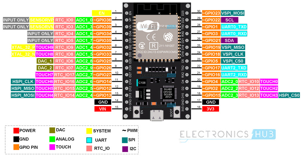
ESP32 OLED Display Interface
Let us now see how to interface an OLED Display with ESP32. First thing to understand is that the communication interface is SPI. So, look at the Pinout of ESP32 and identify the SPI Pins.

From the above image, HSPI and VSPI are available on ESP32 Development Board for SPI Interface. Let us use the VSPI peripheral. The pins for VSPI in ESP32 are:
| VSPI Pin | GPIO Pin |
|---|---|
| VSPI_MOSI | GPIO 23 |
| VSPI_MISO | GPIO 19 |
| VSPI_CLK | GPIO 18 |
| VSPI_CS | GPIO 5 |
NOTE: ESP32 has totally 4 SPI Peripherals. (SPI0, SPI1, HSPI and VSPI). SPI0 is dedicated to SPI Flash IC. SPI1 shares the hardware with SPI0. This leaves HSPI and VSPI for interfacing SPI Devices.
The following table shows the connections between ESP32 and OLED Display Module. In total, we have to make seven connections as this is an SPI OLED Display.
| OLED Display | ESP32 |
|---|---|
| GND | GND |
| VCC | 3.3V |
| D0 (SCK) | GPIO 18 |
| D1 (MOSI) | GPIO 23 |
| RES | GPIO 17 |
| DC | GPIO 16 |
| CS | GPIO 5 |
Components Required
- ESP32 DevKit Development Board
- OLED Display Module
- Breadboard
- Connecting Wires
- Micro USB Cable
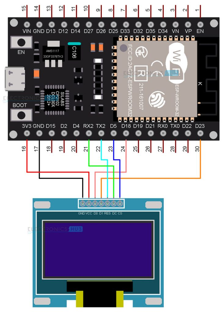
Circuit Diagram
The following image shows the circuit diagram for Interfacing SPI OLED Display with ESP32.
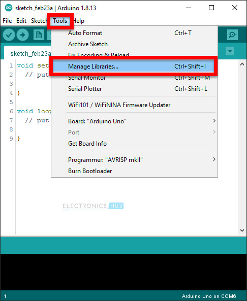
Preparing Arduino IDE
Before writing the code, you need to download some libraries for Arduino IDE related to SSD1306 OLED Display.
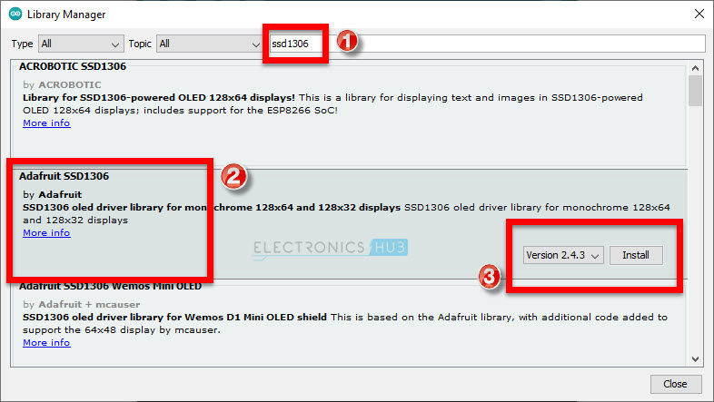
I made a dedicated tutorial on how to install ESP32 Board in Arduino IDE. You can check out that tutorial first. Now, open the Arduino IDE and go to Tools -> Manage Libraries. . .
Arduino-IDE-OLED-Library-1
A Library Manager window will pop-up. In the search bar, type “ssd1306” and from the results select the “Adafruit SSD1306” option and click on install. This library is written specifically for monochrome OLED Displays based on SSD1306 Driver IC. The supported resolutions are 128 x 32 and 128 x 64.

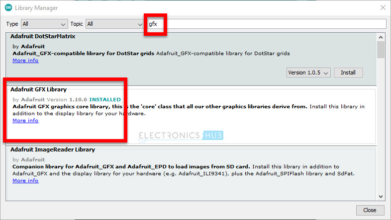
After installing SSD1306 Library, search for “gfx” and install “Adafruit GFX Library”. This is a graphics library by Adafruit for displaying basic graphics like lines, circles, rectangles etc.

Close the library manager window after downloading all the necessary libraries. Now, make sure that ESP32 Board is selected in Arduino IDE (Tools -> Board -> ESP32 Arduino -> ESP32 Dev Module).
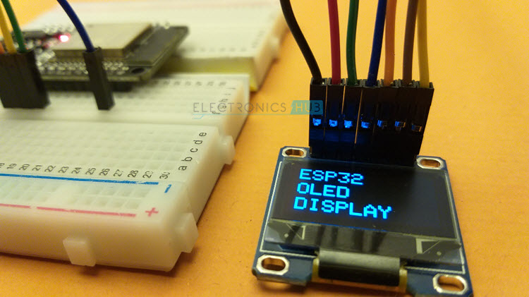
Testing ESP32 OLED Display
After making all the necessary connections, we will now proceed to write a test code for ESP32 to display some text and graphics on the OLED Display. In this code, I am testing various features of the OLED Display like displaying normal text, inverted text, scrolling text, displaying ASCII Characters, setting font size.
I also added the code for displaying graphics like rectangle, filled rectangle, rounded rectangle, filled rounded rectangle, circle, filled circle, triangle and filled triangle.
Finally, I took the “Electronics Hub” logo and converted it into a bitmap and displayed it on the OLED Display.
#include <SPI.h>
#include <Wire.h>
#include <Adafruit_GFX.h>
#include <Adafruit_SSD1306.h>
#define SCREEN_WIDTH 128
#define SCREEN_HEIGHT 64
#define OLED_MOSI 23
#define OLED_CLK 18
#define OLED_DC 16
#define OLED_CS 5
#define OLED_RESET 17
Adafruit_SSD1306 display(SCREEN_WIDTH, SCREEN_HEIGHT,
OLED_MOSI, OLED_CLK, OLED_DC, OLED_RESET, OLED_CS);
const unsigned char electronicshub_logo [] PROGMEM = {
0x00, 0x00, 0x00, 0x00, 0x00, 0x00, 0x00, 0x00, 0x00, 0x00, 0x00, 0x00, 0x00, 0x00, 0x00, 0x00,
0x00, 0x00, 0x00, 0x00, 0x00, 0x00, 0x00, 0x00, 0x00, 0x00, 0x00, 0x00, 0x00, 0x00, 0x00, 0x00,
0x00, 0x00, 0x00, 0x00, 0x00, 0x00, 0x00, 0x00, 0x00, 0x00, 0x00, 0x00, 0x00, 0x00, 0x00, 0x00,
0x00, 0x00, 0x00, 0x00, 0x00, 0x00, 0x00, 0x00, 0x00, 0x00, 0x00, 0x00, 0x00, 0x00, 0x00, 0x00,
0x00, 0x00, 0x00, 0x00, 0x00, 0x00, 0x00, 0x00, 0x00, 0x00, 0x00, 0x00, 0x00, 0x00, 0x00, 0x00,
0x00, 0x00, 0x00, 0x00, 0x00, 0x00, 0x00, 0x00, 0x00, 0x00, 0x00, 0x00, 0x00, 0x00, 0x00, 0x00,
0x00, 0x00, 0x00, 0x00, 0x00, 0x00, 0x00, 0x00, 0x00, 0x00, 0x00, 0x00, 0x00, 0x00, 0x00, 0x00,
0x00, 0x00, 0x00, 0x00, 0x00, 0x00, 0x00, 0x00, 0x00, 0x00, 0x00, 0x00, 0x00, 0x00, 0x00, 0x00,
0x00, 0x00, 0x00, 0x00, 0x00, 0x00, 0x00, 0x00, 0x00, 0x00, 0x00, 0x00, 0x00, 0x00, 0x00, 0x00,
0x00, 0x00, 0x00, 0x00, 0x00, 0x00, 0x00, 0x00, 0x00, 0x00, 0x00, 0x00, 0x00, 0x00, 0x00, 0x00,
0x00, 0x00, 0x00, 0x00, 0x00, 0x00, 0x00, 0x00, 0x00, 0x00, 0x00, 0x00, 0x00, 0x00, 0x00, 0x00,
0x00, 0x00, 0x00, 0x00, 0x00, 0x00, 0x00, 0x00, 0x00, 0x00, 0x00, 0x00, 0x00, 0x00, 0x00, 0x00,
0x00, 0x00, 0x00, 0x00, 0x00, 0x00, 0x00, 0x00, 0x00, 0x00, 0x00, 0x00, 0x00, 0x00, 0x00, 0x00,
0x00, 0x00, 0x00, 0x00, 0x00, 0x00, 0x00, 0x00, 0x00, 0x00, 0x00, 0x0f, 0xff, 0xff, 0xff, 0x80,
0x00, 0x00, 0x00, 0x00, 0x00, 0x00, 0x00, 0x00, 0x00, 0x00, 0x00, 0x0f, 0xff, 0xff, 0xff, 0x80,
0x00, 0x00, 0x00, 0x00, 0x00, 0x00, 0x00, 0x00, 0x00, 0x00, 0x00, 0x0f, 0xff, 0xff, 0xff, 0x80,
0x00, 0x00, 0x00, 0x00, 0x00, 0x00, 0x00, 0x00, 0x00, 0x00, 0x00, 0x0f, 0xff, 0xff, 0xff, 0x80,
0x00, 0x00, 0x00, 0x00, 0x00, 0x00, 0x00, 0x00, 0x00, 0x00, 0x00, 0x0f, 0xff, 0xff, 0xff, 0x80,
0x00, 0x00, 0x00, 0x00, 0x00, 0x00, 0x00, 0x00, 0x00, 0x00, 0x00, 0x0f, 0xff, 0xff, 0xff, 0x80,
0x03, 0xe0, 0x07, 0xc3, 0x87, 0xcf, 0x03, 0x02, 0x11, 0x07, 0x04, 0x0f, 0xbd, 0xbd, 0xc7, 0x80,
0x03, 0xe4, 0x07, 0xc3, 0xc7, 0xcf, 0x07, 0x82, 0x11, 0x07, 0x8e, 0x0f, 0xbd, 0xbd, 0xc7, 0x80,
0x02, 0x04, 0x04, 0x06, 0xc1, 0x01, 0x84, 0xc2, 0x11, 0x0d, 0x8a, 0x0f, 0xbd, 0xbd, 0xf3, 0x80,
0x02, 0x04, 0x04, 0x04, 0x61, 0x00, 0x88, 0x42, 0x11, 0x08, 0x8a, 0x0f, 0xbd, 0xbd, 0xfb, 0x80,
0x02, 0x04, 0x04, 0x0c, 0x21, 0x00, 0x88, 0x43, 0x11, 0x10, 0x08, 0x0f, 0xbd, 0xbd, 0xfb, 0x80,
0x02, 0x04, 0x04, 0x08, 0x01, 0x00, 0x88, 0x23, 0x11, 0x10, 0x08, 0x0f, 0xbd, 0xbd, 0xfb, 0x80,
0x02, 0x04, 0x04, 0x08, 0x01, 0x00, 0x88, 0x23, 0x11, 0x10, 0x08, 0x0f, 0xbd, 0xbd, 0xfb, 0x80,
0x02, 0x04, 0x04, 0x08, 0x01, 0x00, 0x90, 0x23, 0x11, 0x10, 0x08, 0x0f, 0xbd, 0xbd, 0xfb, 0x80,
0x02, 0x04, 0x04, 0x08, 0x01, 0x00, 0x90, 0x22, 0x91, 0x10, 0x08, 0x0f, 0xbd, 0xbd, 0xf7, 0x80,
0x02, 0x04, 0x04, 0x08, 0x01, 0x00, 0x90, 0x22, 0x91, 0x10, 0x0e, 0x0f, 0xbd, 0xbd, 0xc7, 0x80,
0x03, 0x84, 0x07, 0x08, 0x01, 0x00, 0x90, 0x22, 0x91, 0x10, 0x06, 0x0f, 0x81, 0xbd, 0xc7, 0x80,
0x03, 0x84, 0x07, 0x08, 0x01, 0x07, 0x90, 0x22, 0xd1, 0x10, 0x03, 0x0f, 0x81, 0xbd, 0xf7, 0x80,
0x02, 0x04, 0x04, 0x08, 0x01, 0x07, 0x10, 0x22, 0x51, 0x10, 0x01, 0x0f, 0xbd, 0xbd, 0xfb, 0x80,
0x02, 0x04, 0x04, 0x08, 0x01, 0x06, 0x10, 0x22, 0x51, 0x10, 0x01, 0x0f, 0xbd, 0xbd, 0xfb, 0x80,
0x02, 0x04, 0x04, 0x08, 0x01, 0x02, 0x10, 0x22, 0x51, 0x10, 0x01, 0x0f, 0xbd, 0xbd, 0xfb, 0x80,
0x02, 0x04, 0x04, 0x08, 0x01, 0x02, 0x08, 0x22, 0x31, 0x10, 0x01, 0x0f, 0xbd, 0xbd, 0xfb, 0x80,
0x02, 0x04, 0x04, 0x08, 0x01, 0x01, 0x08, 0x22, 0x31, 0x10, 0x01, 0x0f, 0xbd, 0xbd, 0xfb, 0x80,
0x02, 0x04, 0x04, 0x0c, 0x21, 0x01, 0x08, 0x42, 0x31, 0x10, 0x01, 0x0f, 0xbd, 0xdb, 0xfb, 0x80,
0x02, 0x04, 0x04, 0x04, 0x61, 0x01, 0x88, 0x42, 0x31, 0x08, 0x99, 0x0f, 0xbd, 0xdb, 0xf3, 0x80,
0x02, 0x04, 0x04, 0x06, 0xc1, 0x00, 0x84, 0xc2, 0x11, 0x0d, 0x8b, 0x0f, 0xbd, 0xc3, 0xc7, 0x80,
0x03, 0xe7, 0xc7, 0xc3, 0xc1, 0x00, 0x87, 0x82, 0x11, 0x07, 0x8e, 0x0f, 0xbd, 0xe7, 0xc7, 0x80,
0x03, 0xe7, 0xc7, 0xc3, 0x81, 0x00, 0x83, 0x02, 0x11, 0x07, 0x06, 0x0f, 0xff, 0xff, 0xff, 0x80,
0x00, 0x00, 0x00, 0x00, 0x00, 0x00, 0x00, 0x00, 0x00, 0x00, 0x00, 0x0f, 0xff, 0xff, 0xff, 0x80,
0x00, 0x00, 0x00, 0x00, 0x00, 0x00, 0x00, 0x00, 0x00, 0x00, 0x00, 0x0f, 0xff, 0xff, 0xff, 0x80,
0x00, 0x00, 0x00, 0x00, 0x00, 0x00, 0x00, 0x00, 0x00, 0x00, 0x00, 0x0f, 0xff, 0xff, 0xff, 0x80,
0x00, 0x00, 0x00, 0x00, 0x00, 0x00, 0x00, 0x00, 0x00, 0x00, 0x00, 0x0f, 0xff, 0xff, 0xff, 0x80,
0x00, 0x00, 0x00, 0x00, 0x00, 0x00, 0x00, 0x00, 0x00, 0x00, 0x00, 0x0f, 0xff, 0xff, 0xff, 0x80,
0x07, 0xff, 0xff, 0xff, 0xff, 0xff, 0xff, 0xff, 0xff, 0xff, 0xff, 0xff, 0xff, 0xff, 0xff, 0x80,
0x07, 0xff, 0xff, 0xff, 0xff, 0xff, 0xff, 0xff, 0xff, 0xff, 0xff, 0xff, 0xff, 0xff, 0xff, 0x80,
0x00, 0x02, 0x00, 0x00, 0x00, 0x00, 0x00, 0x00, 0x00, 0x00, 0x00, 0x00, 0x00, 0x00, 0x00, 0x00,
0x00, 0x02, 0x00, 0x00, 0x00, 0x00, 0x00, 0x00, 0x00, 0x00, 0x00, 0x00, 0x00, 0x00, 0x00, 0x00,
0x00, 0x02, 0x00, 0x00, 0x00, 0x00, 0x00, 0x00, 0x00, 0x00, 0x00, 0x00, 0x00, 0x00, 0x00, 0x00,
0x00, 0x02, 0x00, 0x00, 0x00, 0x00, 0x00, 0x00, 0x00, 0x00, 0x00, 0x00, 0x00, 0x00, 0x00, 0x00,
0x00, 0x04, 0x00, 0x00, 0x00, 0x00, 0x00, 0x00, 0x00, 0x00, 0x00, 0x00, 0x00, 0x00, 0x00, 0x00,
0x00, 0x04, 0x00, 0x00, 0x00, 0x00, 0x00, 0x00, 0x00, 0x00, 0x00, 0x00, 0x00, 0x00, 0x00, 0x00,
0x00, 0x04, 0x00, 0x00, 0x00, 0x00, 0x00, 0x00, 0x00, 0x00, 0x00, 0x00, 0x00, 0x00, 0x00, 0x00,
0x00, 0x08, 0x00, 0x00, 0x00, 0x00, 0x00, 0x00, 0x00, 0x00, 0x00, 0x00, 0x00, 0x00, 0x00, 0x00,
0x07, 0xf0, 0x00, 0x00, 0x00, 0x00, 0x00, 0x00, 0x00, 0x00, 0x00, 0x00, 0x00, 0x00, 0x00, 0x00,
0x00, 0x00, 0x00, 0x00, 0x00, 0x00, 0x00, 0x00, 0x00, 0x00, 0x00, 0x00, 0x00, 0x00, 0x00, 0x00,
0x00, 0x00, 0x00, 0x00, 0x00, 0x00, 0x00, 0x00, 0x00, 0x00, 0x00, 0x00, 0x00, 0x00, 0x00, 0x00,
0x00, 0x00, 0x00, 0x00, 0x00, 0x00, 0x00, 0x00, 0x00, 0x00, 0x00, 0x00, 0x00, 0x00, 0x00, 0x00,
0x00, 0x00, 0x00, 0x00, 0x00, 0x00, 0x00, 0x00, 0x00, 0x00, 0x00, 0x00, 0x00, 0x00, 0x00, 0x00,
0x00, 0x00, 0x00, 0x00, 0x00, 0x00, 0x00, 0x00, 0x00, 0x00, 0x00, 0x00, 0x00, 0x00, 0x00, 0x00,
0x00, 0x00, 0x00, 0x00, 0x00, 0x00, 0x00, 0x00, 0x00, 0x00, 0x00, 0x00, 0x00, 0x00, 0x00, 0x00,
0x00, 0x00, 0x00, 0x00, 0x00, 0x00, 0x00, 0x00, 0x00, 0x00, 0x00, 0x00, 0x00, 0x00, 0x00, 0x00
};
void setup()
{
Serial.begin(115200);
if(!display.begin(SSD1306_SWITCHCAPVCC))
{
Serial.println(F("SSD1306 allocation failed"));
for(;;);
}
display.clearDisplay();
display.display();
delay(1000);
display.clearDisplay();
display.drawBitmap(0, 0, electronicshub_logo, SCREEN_WIDTH, SCREEN_HEIGHT, SSD1306_WHITE);
display.display();
delay(1000);
}
void loop()
{
AllPixels();
TextDisplay();
InvertedTextDisplay();
ScrollText();
DisplayChars();
TextSize();
DrawRectangle();
DrawFilledRectangle();
DrawRoundRectangle();
DrawFilledRoundRectangle();
DrawCircle();
DrawFilledCircle();
DrawTriangle();
DrawFilledTriangle();
}
void AllPixels()
{
int i;
int j;
display.clearDisplay();
for(i=0;i<64;i++)
{
for(j=0;j<128;j++)
{
display.drawPixel(j, i, SSD1306_WHITE);
}
display.display();
delay(30);
}
for(i=0;i<64;i++)
{
for(j=0;j<128;j++)
{
display.drawPixel(j, i, SSD1306_BLACK);
}
display.display();
delay(30);
}
}
void TextDisplay()
{
display.clearDisplay();
display.setTextSize(1);
display.setTextColor(SSD1306_WHITE);
display.setCursor(5,28);
display.println("Electronics Hub");
display.display();
delay(3000);
}
void InvertedTextDisplay()
{
display.clearDisplay();
display.setTextColor(SSD1306_BLACK, SSD1306_WHITE);
display.setCursor(5,28);
display.println("Electronics Hub");
display.display();
delay(3000);
}
void ScrollText()
{
display.clearDisplay();
display.setCursor(0,0);
display.setTextSize(1);
display.setTextColor(SSD1306_WHITE);
display.println("This is a");
display.println("Scrolling");
display.println("Text!");
display.display();
delay(100);
display.startscrollright(0x00, 0x0F);
delay(2000);
//display.stopscroll();
//delay(1000);
display.startscrollleft(0x00, 0x0F);
delay(2000);
//display.stopscroll();
//delay(1000);
display.startscrolldiagright(0x00, 0x0F);
delay(2000);
display.startscrolldiagleft(0x00, 0x0F);
delay(2000);
display.stopscroll();
}
void DisplayChars()
{
display.clearDisplay();
display.setTextSize(1);
display.setTextColor(SSD1306_WHITE);
display.setCursor(0, 0);
display.cp437(true);
for(int16_t i=0; i<256; i++)
{
if(i == '\n')
{
display.write(' ');
}
else
{
display.write(i);
}
}
display.display();
delay(4000);
}
void TextSize()
{
display.clearDisplay();
display.setTextSize(1);
display.setTextColor(SSD1306_WHITE);
display.setCursor(0,0);
display.println(F("Size: 1"));
display.println(F("ABC"));
display.setTextSize(2);
display.setTextColor(SSD1306_WHITE);
display.println("Size: 2");
display.println(F("ABC"));
display.display();
delay(3000);
}
void DrawRectangle()
{
display.clearDisplay();
display.setTextSize(1);
display.setTextColor(WHITE);
display.setCursor(0,0);
display.println("Rectangle");
display.drawRect(0, 15, 90, 45, SSD1306_WHITE);
display.display();
delay(2000);
}
void DrawFilledRectangle()
{
display.clearDisplay();
display.setTextSize(1);
display.setTextColor(WHITE);
display.setCursor(0,0);
display.println("Filled Rectangle");
display.fillRect(0, 15, 90, 45, SSD1306_WHITE);
display.display();
delay(2000);
}
void DrawRoundRectangle()
{
display.clearDisplay();
display.setTextSize(1);
display.setTextColor(SSD1306_WHITE);
display.setCursor(0,0);
display.println("Round Rectangle");
display.drawRoundRect(0, 15, 90, 45, 10, SSD1306_WHITE);
display.display();
delay(2000);
}
void DrawFilledRoundRectangle()
{
display.clearDisplay();
display.setTextSize(1);
display.setTextColor(SSD1306_WHITE);
display.setCursor(0,0);
display.println("Filled Round Rect");
display.fillRoundRect(0, 15, 90, 45, 10, SSD1306_WHITE);
display.display();
delay(2000);
}
void DrawCircle()
{
display.clearDisplay();
display.setTextSize(1);
display.setTextColor(SSD1306_WHITE);
display.setCursor(0,0);
display.println("Circle");
display.drawCircle(30, 36, 25, SSD1306_WHITE);
display.display();
delay(2000);
}
void DrawFilledCircle()
{
display.clearDisplay();
display.setTextSize(1);
display.setTextColor(SSD1306_WHITE);
display.setCursor(0,0);
display.println("Filled Circle");
display.fillCircle(30, 36, 25, SSD1306_WHITE);
display.display();
delay(2000);
}
void DrawTriangle()
{
display.clearDisplay();
display.setTextSize(1);
display.setTextColor(SSD1306_WHITE);
display.setCursor(0,0);
display.println("Triangle");
display.drawTriangle(30, 15, 0, 60, 60, 60, SSD1306_WHITE);
display.display();
delay(2000);
}
void DrawFilledTriangle()
{
display.clearDisplay();
display.setTextSize(1);
display.setTextColor(SSD1306_WHITE);
display.setCursor(0,0);
display.println("Filled Triangle");
display.fillTriangle(30, 15, 0, 60, 60, 60, SSD1306_WHITE);
display.display();
delay(2000);
}
Conclusion
A simple tutorial on how to interface SPI OLED Display Module with ESP32 DevKit Board. You learned the pinout of SSD1306 OLED Display, necessary connections for SPI Interface with ESP32, download libraries for Arduino IDE and display some text, graphics and image on the OLED Display using ESP32.
Энкодер
Схема подключения

Код
#define CLK 2 // Указываем к какому выводу CLK энкодер подключен к Arduino
#define DT 3 // Указываем к какому выводу DT энкодер подключен к Arduino
#define SW 4 // Указываем к какому выводу SW энкодер подключен к Arduino
int counter = 0; // Создаем переменную counter
int currentStateCLK; // Создаем переменную currentStateCLK
int lastStateCLK; // Создаем переменную lastStateCLK
String currentDir =""; // Создаем
unsigned long lastButtonPress = 0; // Создаем переменную lastBut
void setup()
{
pinMode(CLK, INPUT); // Указываем вывод CLK как вход
pinMode(DT, INPUT); // Указываем вывод DT как вход
pinMode(SW, INPUT_PULLUP); // Указываем вывод SW как вход и включаем подтягивающий резистор
Serial.begin(9600); // Создаем последовательную связь
lastStateCLK = digitalRead(CLK);
pinMode(13, OUTPUT); // Считываем значение с CLK
}
void loop()
{
currentStateCLK = digitalRead(CLK); // Считываем значение с CLK
// Проверяем изменилось ли состояние CLK
if (currentStateCLK != lastStateCLK && currentStateCLK == 1){
if (digitalRead(DT) != currentStateCLK) {
counter --;
currentDir ="CCW";
} else {
counter ++;
currentDir ="CW";
}
Serial.print("Direction: ");
Serial.print(currentDir);
Serial.print(" | Counter: ");
Serial.println(counter);
}
lastStateCLK = currentStateCLK; // Запопоследнее состояние CLK
int btnState = digitalRead(SW); // Считываем состояние вывода SW
if (btnState == LOW){ // Если состояние LOW, кнопка нажата
if (millis() - lastButtonPress > 50){ // Если состояние LOW в течении 50 мкс, кнопка нажата
Serial.println("Button pressed!"); // ОТправка сообщения
switch (digitalRead(13)) { // переводим светодиод в противоположное состояние
case HIGH:
digitalWrite(13, LOW);
break;
case LOW:
digitalWrite(13, HIGH);
break;
}
}
lastButtonPress = millis();
}
delay(1); // Пауза
}
Esp
Обзор микроконтроллера ESP8266
Как взаимодействовать с OLED дисплеем с помощью ESP32? ESP32 OLED Display инструкция
In this tutorial, we will learn how to interface an OLED Display Module with ESP32 Development Board. The OLED Graphic Display used in this project is based on SSD1306 OLED Driver IC and communicates over SPI. Use ESP32 with OLED to display Text, Bitmap Images, Graphics etc., in your DIY project.
 SPI-OLED-Display-ESP32-1
Outline
OLED Display
OLED or Organic Light Emitting Diode is an advance display technology which uses a film of organic compound between two electrodes (anode and cathode) and when voltage is applied across the electrodes, the organic film emits light.
The main advantage of an OLED Display is that it emits its own light and doesn’t need another source of backlight. Due to this, OLED Displays often have better contrast, brightness and viewing angles when compared to LCD displays.
Another important feature of OLED Displays is deep black levels. Since each pixel emits its own light in an OLED Display, to produce black color, the individual pixel can be turned OFF.
A Brief Note on SSD1306 OLED Display
Do you want to use an OLED Display in your DIY Project? Do you want to display important information like IP Address, Web Server Address etc., on a display? Then the SSD1306 OLED Display Module is the perfect option.
 SPI-OLED-Display-Module
This display module consists of a Monochrome OLED Display with a resolution of 128 pixels by 64 pixels. It measures 0.96” diagonally. This OLED Display is using the SSD1306 OLED Driver IC.
SSD1306 OLED Displays have three types of communication interfaces:
- 8-bit 6800 Parallel Interface
- 3 or 4 wire SPI
- I2C Of these, the I2C and SPI type OLEDs are very common. It is possible of change the configuration from SPI to I2C and vice-versa (you have solder / de-solder some SMD resistors). The model that I have is using 4-wire SPI Communication.
 SPI-OLED-Display-Module-Front-Back
The SSD1306 OLED Driver IC has 128 x 64 bits Graphic Display Data RAM (GDDRAM). It is divided into eight pages (PAGE 0 to PAGE 7) and each page has 128 Segments. Again, each segment consists of 8-bits and each bit represents one pixel of the display.
So, 8 Pages * 128 Segments * 8 Bits = 8192 Bits (1024 Bytes).
 SSD1306-RAM
Pinout of OLED Display Module
The following table shows the Pinout of 7-pin SPI based OLED Display Module.
| Pin (Alternative Names) | Description |
|---|---|
| GND | Ground |
| VCC | Power Supply |
| D0 (SCK, SCL, CLK) | Clock |
| D1 (MOSI, SDA) | Data |
| RES (RST) | Reset |
| DC (A0) | Data / Command Selection |
| CS | Chip Select |
 SPI-OLED-Display-Pinout
Power Supply
The SSD1306 OLED Driver IC runs on VDD = 1.65V to 3.3V and the actual OLED Panel runs on VCC = 7V to 15V. The OLED Display Module takes care of these wide ranges of voltage requirements with a charge pump circuit (for Panel) and regulator (for Driver IC) from a single power supply (usually between 3V and 5V).
This makes the OLED Display Module to be connected to different boards like Arduino (with 5V logic) and ESP32 (with 3.3V logic).
ESP32 OLED Display Interface
Let us now see how to interface an OLED Display with ESP32. First thing to understand is that the communication interface is SPI. So, look at the Pinout of ESP32 and identify the SPI Pins.
 ESP32-Pinout
From the above image, HSPI and VSPI are available on ESP32 Development Board for SPI Interface. Let us use the VSPI peripheral. The pins for VSPI in ESP32 are:
| VSPI Pin | GPIO Pin | | VSPI_MOSI | GPIO 23 | | VSPI_MISO |GPIO 19| | VSPI_CLK |GPIO 18| | VSPI_CS | GPIO 5 |
NOTE: ESP32 has totally 4 SPI Peripherals. (SPI0, SPI1, HSPI and VSPI). SPI0 is dedicated to SPI Flash IC. SPI1 shares the hardware with SPI0. This leaves HSPI and VSPI for interfacing SPI Devices.
The following table shows the connections between ESP32 and OLED Display Module. In total, we have to make seven connections as this is an SPI OLED Display.
|OLED Display | ESP32 | | GND |GND| | VCC | 3.3V | | D0 (SCK) | GPIO 18 | | D1 (MOSI) | GPIO 23| | RES | GPIO 17| | DC | GPIO 16 | | CS | GPIO 5|
Components RequiredESP32-OLED-Display-Circuit-Diagram
- ESP32 DevKit Development Board
- OLED Display Module
- Breadboard
- Connecting Wires
- Micro USB Cable
Circuit Diagram
The following image shows the circuit diagram for Interfacing SPI OLED Display with ESP32.
 ESP32-OLED-Display-Circuit-Diagram
Preparing Arduino IDE
Before writing the code, you need to download some libraries for Arduino IDE related to SSD1306 OLED Display.
I made a dedicated tutorial on how to install ESP32 Board in Arduino IDE. You can check out that tutorial first. Now, open the Arduino IDE and go to Tools -> Manage Libraries. . .
 Arduino-IDE-OLED-Library-1
A Library Manager window will pop-up. In the search bar, type “ssd1306” and from the results select the “Adafruit SSD1306” option and click on install. This library is written specifically for monochrome OLED Displays based on SSD1306 Driver IC. The supported resolutions are 128 x 32 and 128 x 64.
 Arduino-IDE-OLED-Library-2
After installing SSD1306 Library, search for “gfx” and install “Adafruit GFX Library”. This is a graphics library by Adafruit for displaying basic graphics like lines, circles, rectangles etc.
 Arduino-IDE-OLED-Library-3
Close the library manager window after downloading all the necessary libraries. Now, make sure that ESP32 Board is selected in Arduino IDE (Tools -> Board -> ESP32 Arduino -> ESP32 Dev Module).
Testing ESP32 OLED Display
After making all the necessary connections, we will now proceed to write a test code for ESP32 to display some text and graphics on the OLED Display. In this code, I am testing various features of the OLED Display like displaying normal text, inverted text, scrolling text, displaying ASCII Characters, setting font size.
I also added the code for displaying graphics like rectangle, filled rectangle, rounded rectangle, filled rounded rectangle, circle, filled circle, triangle and filled triangle.
Finally, I took the “Electronics Hub” logo and converted it into a bitmap and displayed it on the OLED Display.
#include <SPI.h>
#include <Wire.h>
#include <Adafruit_GFX.h>
#include <Adafruit_SSD1306.h>
#define SCREEN_WIDTH 128
#define SCREEN_HEIGHT 64
#define OLED_MOSI 23
#define OLED_CLK 18
#define OLED_DC 16
#define OLED_CS 5
#define OLED_RESET 17
Adafruit_SSD1306 display(SCREEN_WIDTH, SCREEN_HEIGHT,
OLED_MOSI, OLED_CLK, OLED_DC, OLED_RESET, OLED_CS);
const unsigned char electronicshub_logo [] PROGMEM = {
0x00, 0x00, 0x00, 0x00, 0x00, 0x00, 0x00, 0x00, 0x00, 0x00, 0x00, 0x00, 0x00, 0x00, 0x00, 0x00,
0x00, 0x00, 0x00, 0x00, 0x00, 0x00, 0x00, 0x00, 0x00, 0x00, 0x00, 0x00, 0x00, 0x00, 0x00, 0x00,
0x00, 0x00, 0x00, 0x00, 0x00, 0x00, 0x00, 0x00, 0x00, 0x00, 0x00, 0x00, 0x00, 0x00, 0x00, 0x00,
0x00, 0x00, 0x00, 0x00, 0x00, 0x00, 0x00, 0x00, 0x00, 0x00, 0x00, 0x00, 0x00, 0x00, 0x00, 0x00,
0x00, 0x00, 0x00, 0x00, 0x00, 0x00, 0x00, 0x00, 0x00, 0x00, 0x00, 0x00, 0x00, 0x00, 0x00, 0x00,
0x00, 0x00, 0x00, 0x00, 0x00, 0x00, 0x00, 0x00, 0x00, 0x00, 0x00, 0x00, 0x00, 0x00, 0x00, 0x00,
0x00, 0x00, 0x00, 0x00, 0x00, 0x00, 0x00, 0x00, 0x00, 0x00, 0x00, 0x00, 0x00, 0x00, 0x00, 0x00,
0x00, 0x00, 0x00, 0x00, 0x00, 0x00, 0x00, 0x00, 0x00, 0x00, 0x00, 0x00, 0x00, 0x00, 0x00, 0x00,
0x00, 0x00, 0x00, 0x00, 0x00, 0x00, 0x00, 0x00, 0x00, 0x00, 0x00, 0x00, 0x00, 0x00, 0x00, 0x00,
0x00, 0x00, 0x00, 0x00, 0x00, 0x00, 0x00, 0x00, 0x00, 0x00, 0x00, 0x00, 0x00, 0x00, 0x00, 0x00,
0x00, 0x00, 0x00, 0x00, 0x00, 0x00, 0x00, 0x00, 0x00, 0x00, 0x00, 0x00, 0x00, 0x00, 0x00, 0x00,
0x00, 0x00, 0x00, 0x00, 0x00, 0x00, 0x00, 0x00, 0x00, 0x00, 0x00, 0x00, 0x00, 0x00, 0x00, 0x00,
0x00, 0x00, 0x00, 0x00, 0x00, 0x00, 0x00, 0x00, 0x00, 0x00, 0x00, 0x00, 0x00, 0x00, 0x00, 0x00,
0x00, 0x00, 0x00, 0x00, 0x00, 0x00, 0x00, 0x00, 0x00, 0x00, 0x00, 0x0f, 0xff, 0xff, 0xff, 0x80,
0x00, 0x00, 0x00, 0x00, 0x00, 0x00, 0x00, 0x00, 0x00, 0x00, 0x00, 0x0f, 0xff, 0xff, 0xff, 0x80,
0x00, 0x00, 0x00, 0x00, 0x00, 0x00, 0x00, 0x00, 0x00, 0x00, 0x00, 0x0f, 0xff, 0xff, 0xff, 0x80,
0x00, 0x00, 0x00, 0x00, 0x00, 0x00, 0x00, 0x00, 0x00, 0x00, 0x00, 0x0f, 0xff, 0xff, 0xff, 0x80,
0x00, 0x00, 0x00, 0x00, 0x00, 0x00, 0x00, 0x00, 0x00, 0x00, 0x00, 0x0f, 0xff, 0xff, 0xff, 0x80,
0x00, 0x00, 0x00, 0x00, 0x00, 0x00, 0x00, 0x00, 0x00, 0x00, 0x00, 0x0f, 0xff, 0xff, 0xff, 0x80,
0x03, 0xe0, 0x07, 0xc3, 0x87, 0xcf, 0x03, 0x02, 0x11, 0x07, 0x04, 0x0f, 0xbd, 0xbd, 0xc7, 0x80,
0x03, 0xe4, 0x07, 0xc3, 0xc7, 0xcf, 0x07, 0x82, 0x11, 0x07, 0x8e, 0x0f, 0xbd, 0xbd, 0xc7, 0x80,
0x02, 0x04, 0x04, 0x06, 0xc1, 0x01, 0x84, 0xc2, 0x11, 0x0d, 0x8a, 0x0f, 0xbd, 0xbd, 0xf3, 0x80,
0x02, 0x04, 0x04, 0x04, 0x61, 0x00, 0x88, 0x42, 0x11, 0x08, 0x8a, 0x0f, 0xbd, 0xbd, 0xfb, 0x80,
0x02, 0x04, 0x04, 0x0c, 0x21, 0x00, 0x88, 0x43, 0x11, 0x10, 0x08, 0x0f, 0xbd, 0xbd, 0xfb, 0x80,
0x02, 0x04, 0x04, 0x08, 0x01, 0x00, 0x88, 0x23, 0x11, 0x10, 0x08, 0x0f, 0xbd, 0xbd, 0xfb, 0x80,
0x02, 0x04, 0x04, 0x08, 0x01, 0x00, 0x88, 0x23, 0x11, 0x10, 0x08, 0x0f, 0xbd, 0xbd, 0xfb, 0x80,
0x02, 0x04, 0x04, 0x08, 0x01, 0x00, 0x90, 0x23, 0x11, 0x10, 0x08, 0x0f, 0xbd, 0xbd, 0xfb, 0x80,
0x02, 0x04, 0x04, 0x08, 0x01, 0x00, 0x90, 0x22, 0x91, 0x10, 0x08, 0x0f, 0xbd, 0xbd, 0xf7, 0x80,
0x02, 0x04, 0x04, 0x08, 0x01, 0x00, 0x90, 0x22, 0x91, 0x10, 0x0e, 0x0f, 0xbd, 0xbd, 0xc7, 0x80,
0x03, 0x84, 0x07, 0x08, 0x01, 0x00, 0x90, 0x22, 0x91, 0x10, 0x06, 0x0f, 0x81, 0xbd, 0xc7, 0x80,
0x03, 0x84, 0x07, 0x08, 0x01, 0x07, 0x90, 0x22, 0xd1, 0x10, 0x03, 0x0f, 0x81, 0xbd, 0xf7, 0x80,
0x02, 0x04, 0x04, 0x08, 0x01, 0x07, 0x10, 0x22, 0x51, 0x10, 0x01, 0x0f, 0xbd, 0xbd, 0xfb, 0x80,
0x02, 0x04, 0x04, 0x08, 0x01, 0x06, 0x10, 0x22, 0x51, 0x10, 0x01, 0x0f, 0xbd, 0xbd, 0xfb, 0x80,
0x02, 0x04, 0x04, 0x08, 0x01, 0x02, 0x10, 0x22, 0x51, 0x10, 0x01, 0x0f, 0xbd, 0xbd, 0xfb, 0x80,
0x02, 0x04, 0x04, 0x08, 0x01, 0x02, 0x08, 0x22, 0x31, 0x10, 0x01, 0x0f, 0xbd, 0xbd, 0xfb, 0x80,
0x02, 0x04, 0x04, 0x08, 0x01, 0x01, 0x08, 0x22, 0x31, 0x10, 0x01, 0x0f, 0xbd, 0xbd, 0xfb, 0x80,
0x02, 0x04, 0x04, 0x0c, 0x21, 0x01, 0x08, 0x42, 0x31, 0x10, 0x01, 0x0f, 0xbd, 0xdb, 0xfb, 0x80,
0x02, 0x04, 0x04, 0x04, 0x61, 0x01, 0x88, 0x42, 0x31, 0x08, 0x99, 0x0f, 0xbd, 0xdb, 0xf3, 0x80,
0x02, 0x04, 0x04, 0x06, 0xc1, 0x00, 0x84, 0xc2, 0x11, 0x0d, 0x8b, 0x0f, 0xbd, 0xc3, 0xc7, 0x80,
0x03, 0xe7, 0xc7, 0xc3, 0xc1, 0x00, 0x87, 0x82, 0x11, 0x07, 0x8e, 0x0f, 0xbd, 0xe7, 0xc7, 0x80,
0x03, 0xe7, 0xc7, 0xc3, 0x81, 0x00, 0x83, 0x02, 0x11, 0x07, 0x06, 0x0f, 0xff, 0xff, 0xff, 0x80,
0x00, 0x00, 0x00, 0x00, 0x00, 0x00, 0x00, 0x00, 0x00, 0x00, 0x00, 0x0f, 0xff, 0xff, 0xff, 0x80,
0x00, 0x00, 0x00, 0x00, 0x00, 0x00, 0x00, 0x00, 0x00, 0x00, 0x00, 0x0f, 0xff, 0xff, 0xff, 0x80,
0x00, 0x00, 0x00, 0x00, 0x00, 0x00, 0x00, 0x00, 0x00, 0x00, 0x00, 0x0f, 0xff, 0xff, 0xff, 0x80,
0x00, 0x00, 0x00, 0x00, 0x00, 0x00, 0x00, 0x00, 0x00, 0x00, 0x00, 0x0f, 0xff, 0xff, 0xff, 0x80,
0x00, 0x00, 0x00, 0x00, 0x00, 0x00, 0x00, 0x00, 0x00, 0x00, 0x00, 0x0f, 0xff, 0xff, 0xff, 0x80,
0x07, 0xff, 0xff, 0xff, 0xff, 0xff, 0xff, 0xff, 0xff, 0xff, 0xff, 0xff, 0xff, 0xff, 0xff, 0x80,
0x07, 0xff, 0xff, 0xff, 0xff, 0xff, 0xff, 0xff, 0xff, 0xff, 0xff, 0xff, 0xff, 0xff, 0xff, 0x80,
0x00, 0x02, 0x00, 0x00, 0x00, 0x00, 0x00, 0x00, 0x00, 0x00, 0x00, 0x00, 0x00, 0x00, 0x00, 0x00,
0x00, 0x02, 0x00, 0x00, 0x00, 0x00, 0x00, 0x00, 0x00, 0x00, 0x00, 0x00, 0x00, 0x00, 0x00, 0x00,
0x00, 0x02, 0x00, 0x00, 0x00, 0x00, 0x00, 0x00, 0x00, 0x00, 0x00, 0x00, 0x00, 0x00, 0x00, 0x00,
0x00, 0x02, 0x00, 0x00, 0x00, 0x00, 0x00, 0x00, 0x00, 0x00, 0x00, 0x00, 0x00, 0x00, 0x00, 0x00,
0x00, 0x04, 0x00, 0x00, 0x00, 0x00, 0x00, 0x00, 0x00, 0x00, 0x00, 0x00, 0x00, 0x00, 0x00, 0x00,
0x00, 0x04, 0x00, 0x00, 0x00, 0x00, 0x00, 0x00, 0x00, 0x00, 0x00, 0x00, 0x00, 0x00, 0x00, 0x00,
0x00, 0x04, 0x00, 0x00, 0x00, 0x00, 0x00, 0x00, 0x00, 0x00, 0x00, 0x00, 0x00, 0x00, 0x00, 0x00,
0x00, 0x08, 0x00, 0x00, 0x00, 0x00, 0x00, 0x00, 0x00, 0x00, 0x00, 0x00, 0x00, 0x00, 0x00, 0x00,
0x07, 0xf0, 0x00, 0x00, 0x00, 0x00, 0x00, 0x00, 0x00, 0x00, 0x00, 0x00, 0x00, 0x00, 0x00, 0x00,
0x00, 0x00, 0x00, 0x00, 0x00, 0x00, 0x00, 0x00, 0x00, 0x00, 0x00, 0x00, 0x00, 0x00, 0x00, 0x00,
0x00, 0x00, 0x00, 0x00, 0x00, 0x00, 0x00, 0x00, 0x00, 0x00, 0x00, 0x00, 0x00, 0x00, 0x00, 0x00,
0x00, 0x00, 0x00, 0x00, 0x00, 0x00, 0x00, 0x00, 0x00, 0x00, 0x00, 0x00, 0x00, 0x00, 0x00, 0x00,
0x00, 0x00, 0x00, 0x00, 0x00, 0x00, 0x00, 0x00, 0x00, 0x00, 0x00, 0x00, 0x00, 0x00, 0x00, 0x00,
0x00, 0x00, 0x00, 0x00, 0x00, 0x00, 0x00, 0x00, 0x00, 0x00, 0x00, 0x00, 0x00, 0x00, 0x00, 0x00,
0x00, 0x00, 0x00, 0x00, 0x00, 0x00, 0x00, 0x00, 0x00, 0x00, 0x00, 0x00, 0x00, 0x00, 0x00, 0x00,
0x00, 0x00, 0x00, 0x00, 0x00, 0x00, 0x00, 0x00, 0x00, 0x00, 0x00, 0x00, 0x00, 0x00, 0x00, 0x00
};
void setup()
{
Serial.begin(115200);
if(!display.begin(SSD1306_SWITCHCAPVCC))
{
Serial.println(F("SSD1306 allocation failed"));
for(;;);
}
display.clearDisplay();
display.display();
delay(1000);
display.clearDisplay();
display.drawBitmap(0, 0, electronicshub_logo, SCREEN_WIDTH, SCREEN_HEIGHT, SSD1306_WHITE);
display.display();
delay(1000);
}
void loop()
{
AllPixels();
TextDisplay();
InvertedTextDisplay();
ScrollText();
DisplayChars();
TextSize();
DrawRectangle();
DrawFilledRectangle();
DrawRoundRectangle();
DrawFilledRoundRectangle();
DrawCircle();
DrawFilledCircle();
DrawTriangle();
DrawFilledTriangle();
}
void AllPixels()
{
int i;
int j;
display.clearDisplay();
for(i=0;i<64;i++)
{
for(j=0;j<128;j++)
{
display.drawPixel(j, i, SSD1306_WHITE);
}
display.display();
delay(30);
}
for(i=0;i<64;i++)
{
for(j=0;j<128;j++)
{
display.drawPixel(j, i, SSD1306_BLACK);
}
display.display();
delay(30);
}
}
void TextDisplay()
{
display.clearDisplay();
display.setTextSize(1);
display.setTextColor(SSD1306_WHITE);
display.setCursor(5,28);
display.println("Electronics Hub");
display.display();
delay(3000);
}
void InvertedTextDisplay()
{
display.clearDisplay();
display.setTextColor(SSD1306_BLACK, SSD1306_WHITE);
display.setCursor(5,28);
display.println("Electronics Hub");
display.display();
delay(3000);
}
void ScrollText()
{
display.clearDisplay();
display.setCursor(0,0);
display.setTextSize(1);
display.setTextColor(SSD1306_WHITE);
display.println("This is a");
display.println("Scrolling");
display.println("Text!");
display.display();
delay(100);
display.startscrollright(0x00, 0x0F);
delay(2000);
//display.stopscroll();
//delay(1000);
display.startscrollleft(0x00, 0x0F);
delay(2000);
//display.stopscroll();
//delay(1000);
display.startscrolldiagright(0x00, 0x0F);
delay(2000);
display.startscrolldiagleft(0x00, 0x0F);
delay(2000);
display.stopscroll();
}
void DisplayChars()
{
display.clearDisplay();
display.setTextSize(1);
display.setTextColor(SSD1306_WHITE);
display.setCursor(0, 0);
display.cp437(true);
for(int16_t i=0; i<256; i++)
{
if(i == '\n')
{
display.write(' ');
}
else
{
display.write(i);
}
}
display.display();
delay(4000);
}
void TextSize()
{
display.clearDisplay();
display.setTextSize(1);
display.setTextColor(SSD1306_WHITE);
display.setCursor(0,0);
display.println(F("Size: 1"));
display.println(F("ABC"));
display.setTextSize(2);
display.setTextColor(SSD1306_WHITE);
display.println("Size: 2");
display.println(F("ABC"));
display.display();
delay(3000);
}
void DrawRectangle()
{
display.clearDisplay();
display.setTextSize(1);
display.setTextColor(WHITE);
display.setCursor(0,0);
display.println("Rectangle");
display.drawRect(0, 15, 90, 45, SSD1306_WHITE);
display.display();
delay(2000);
}
void DrawFilledRectangle()
{
display.clearDisplay();
display.setTextSize(1);
display.setTextColor(WHITE);
display.setCursor(0,0);
display.println("Filled Rectangle");
display.fillRect(0, 15, 90, 45, SSD1306_WHITE);
display.display();
delay(2000);
}
void DrawRoundRectangle()
{
display.clearDisplay();
display.setTextSize(1);
display.setTextColor(SSD1306_WHITE);
display.setCursor(0,0);
display.println("Round Rectangle");
display.drawRoundRect(0, 15, 90, 45, 10, SSD1306_WHITE);
display.display();
delay(2000);
}
void DrawFilledRoundRectangle()
{
display.clearDisplay();
display.setTextSize(1);
display.setTextColor(SSD1306_WHITE);
display.setCursor(0,0);
display.println("Filled Round Rect");
display.fillRoundRect(0, 15, 90, 45, 10, SSD1306_WHITE);
display.display();
delay(2000);
}
void DrawCircle()
{
display.clearDisplay();
display.setTextSize(1);
display.setTextColor(SSD1306_WHITE);
display.setCursor(0,0);
display.println("Circle");
display.drawCircle(30, 36, 25, SSD1306_WHITE);
display.display();
delay(2000);
}
void DrawFilledCircle()
{
display.clearDisplay();
display.setTextSize(1);
display.setTextColor(SSD1306_WHITE);
display.setCursor(0,0);
display.println("Filled Circle");
display.fillCircle(30, 36, 25, SSD1306_WHITE);
display.display();
delay(2000);
}
void DrawTriangle()
{
display.clearDisplay();
display.setTextSize(1);
display.setTextColor(SSD1306_WHITE);
display.setCursor(0,0);
display.println("Triangle");
display.drawTriangle(30, 15, 0, 60, 60, 60, SSD1306_WHITE);
display.display();
delay(2000);
}
void DrawFilledTriangle()
{
display.clearDisplay();
display.setTextSize(1);
display.setTextColor(SSD1306_WHITE);
display.setCursor(0,0);
display.println("Filled Triangle");
display.fillTriangle(30, 15, 0, 60, 60, 60, SSD1306_WHITE);
display.display();
delay(2000);
}
Conclusion
A simple tutorial on how to interface SPI OLED Display Module with ESP32 DevKit Board. You learned the pinout of SSD1306 OLED Display, necessary connections for SPI Interface with ESP32, download libraries for Arduino IDE and display some text, graphics and image on the OLED Display using ESP32.
Related Posts:
How to Interface OLED Display with NodeMCU ESP8266? OLED Display Technology Interfacing I2C LCD with ESP32 | ESP32 I2C LCD Tutorial ESP32 BMP180 Sensor Tutorial | How to Interface… ESP32 DS18B20 Tutorial | DS18B20 Temperature Sensor… ESP32 DHT11 Tutorial | DHT11 Humidity Temperature…
mqtt
How to use MQTT in Golang
Golang is a statically strongly typed, compiled, concurrent, and garbage-collecting programming language developed by Google. Go is expressive, clean, and efficient. Its concurrency mechanism makes it easy to write programs that maximize the use of multicore and network machines, and its innovative type system enables flexible and modular program construction. Go compiles quickly to machine code, but with the convenience of garbage collection and the power of runtime reflection. It is a fast, statically typed, compiled language, like a dynamically typed, interpreted language.
MQTT is a kind of lightweight IoT messaging protocol based on the publish/subscribe model, which can provide real-time and reliable messaging service for IoT devices, only using very little code and bandwidth. It is suitable for devices with limited hardware resources and the network environment with limited bandwidth. Therefore, MQTT protocol is widely used in IoT, mobile internet, IoV, electricity power, and other industries.
This article mainly introduces how to use paho.mqtt.golang client library in the Golang project, and implement the connection, subscription and messaging between the client and the MQTT broker.
Project initialization
This project is based on go 1.13.12 to develop and test.
go version go version go1.13.12 darwin/amd64 This project uses paho.mqtt.golang as MQTT client library, install:
go get github.com/eclipse/paho.mqtt.golang
Use of Go MQTT
This article will use the free public MQTT broker provided by EMQX. This service is based on the MQTT IoT cloud platform of EMQX to create. The access information of the server is as follows:
- Broker: broker.emqx.io
- TCP Port: 1883
- Websocket Port: 8083 Connect to the MQTT broker
package main
import (
"fmt"
mqtt "github.com/eclipse/paho.mqtt.golang"
"time"
)
var messagePubHandler mqtt.MessageHandler = func(client mqtt.Client, msg mqtt.Message) {
fmt.Printf("Received message: %s from topic: %s\n", msg.Payload(), msg.Topic())
}
var connectHandler mqtt.OnConnectHandler = func(client mqtt.Client) {
fmt.Println("Connected")
}
var connectLostHandler mqtt.ConnectionLostHandler = func(client mqtt.Client, err error) {
fmt.Printf("Connect lost: %v", err)
}
func main() {
var broker = "broker.emqx.io"
var port = 1883
opts := mqtt.NewClientOptions()
opts.AddBroker(fmt.Sprintf("tcp://%s:%d", broker, port))
opts.SetClientID("go_mqtt_client")
opts.SetUsername("emqx")
opts.SetPassword("public")
opts.SetDefaultPublishHandler(messagePubHandler)
opts.OnConnect = connectHandler
opts.OnConnectionLost = connectLostHandler
client := mqtt.NewClient(opts)
if token := client.Connect(); token.Wait() && token.Error() != nil {
panic(token.Error())
}
}
- ClientOptions: used to set broker, port, client id, username, password and other options.
-
messagePubHandler: global MQTT pub message processing -
connectHandler: callback for the connection -
connectLostHandler: callback for connection loss If you want to use the TSL connection, you can use the following settings:
func NewTlsConfig() *tls.Config {
certpool := x509.NewCertPool()
ca, err := ioutil.ReadFile("ca.pem")
if err != nil {
log.Fatalln(err.Error())
}
certpool.AppendCertsFromPEM(ca)
// Import client certificate/key pair
clientKeyPair, err := tls.LoadX509KeyPair("client-crt.pem", "client-key.pem")
if err != nil {
panic(err)
}
return &tls.Config{
RootCAs: certpool,
ClientAuth: tls.NoClientCert,
ClientCAs: nil,
InsecureSkipVerify: true,
Certificates: []tls.Certificate{clientKeyPair},
}
}
If the client certificate is not set, it can be set as follows:
func NewTlsConfig() *tls.Config {
certpool := x509.NewCertPool()
ca, err := ioutil.ReadFile("ca.pem")
if err != nil {
log.Fatalln(err.Error())
}
certpool.AppendCertsFromPEM(ca)
return &tls.Config{
RootCAs: certpool,
}
Then set TLS
var broker = "broker.emqx.io"
var port = 8883
opts := mqtt.NewClientOptions()
opts.AddBroker(fmt.Sprintf("ssl://%s:%d", broker, port))
tlsConfig := NewTlsConfig()
opts.SetTLSConfig(tlsConfig)
// other options
Subscription
func sub(client mqtt.Client) {
topic := "topic/test"
token := client.Subscribe(topic, 1, nil)
token.Wait()
fmt.Printf("Subscribed to topic %s", topic)
}
Publish messages
func publish(client mqtt.Client) {
num := 10
for i := 0; i < num; i++ {
text := fmt.Sprintf("Message %d", i)
token := client.Publish("topic/test", 0, false, text)
token.Wait()
time.Sleep(time.Second)
}
}
Test We use the following code for testing.
package main
import ( "fmt" mqtt "github.com/eclipse/paho.mqtt.golang" "log" "time" )
var messagePubHandler mqtt.MessageHandler = func(client mqtt.Client, msg mqtt.Message) { fmt.Printf("Received message: %s from topic: %s\n", msg.Payload(), msg.Topic()) }
var connectHandler mqtt.OnConnectHandler = func(client mqtt.Client) { fmt.Println("Connected") }
var connectLostHandler mqtt.ConnectionLostHandler = func(client mqtt.Client, err error) { fmt.Printf("Connect lost: %v", err) }
func main() { var broker = "broker.emqx.io" var port = 1883 opts := mqtt.NewClientOptions() opts.AddBroker(fmt.Sprintf("tcp://%s:%d", broker, port)) opts.SetClientID("go_mqtt_client") opts.SetUsername("emqx") opts.SetPassword("public") opts.SetDefaultPublishHandler(messagePubHandler) opts.OnConnect = connectHandler opts.OnConnectionLost = connectLostHandler client := mqtt.NewClient(opts) if token := client.Connect(); token.Wait() && token.Error() != nil { panic(token.Error()) }
sub(client)
publish(client)
client.Disconnect(250)
}
func publish(client mqtt.Client) { num := 10 for i := 0; i < num; i++ { text := fmt.Sprintf("Message %d", i) token := client.Publish("topic/test", 0, false, text) token.Wait() time.Sleep(time.Second) } }
func sub(client mqtt.Client) { topic := "topic/test" token := client.Subscribe(topic, 1, nil) token.Wait() fmt.Printf("Subscribed to topic: %s", topic) } Run code, we can see that the MQTT connection and subscription are successfully, and we can successfully receive the message of subscribing topic. gomqtt.png
Summary So far, we have completed using the paho.mqtt.golang client to connect to the public MQTT broker and have implemented the connection, message publishing and subscription between the test client and the MQTT broker.
Next, you can check out The Easy-to-understand Guide to MQTT Protocol series of articles provided by EMQ to learn about MQTT protocol features, explore more advanced applications of MQTT, and get started with MQTT application and service development.
raspberry
Общая информация
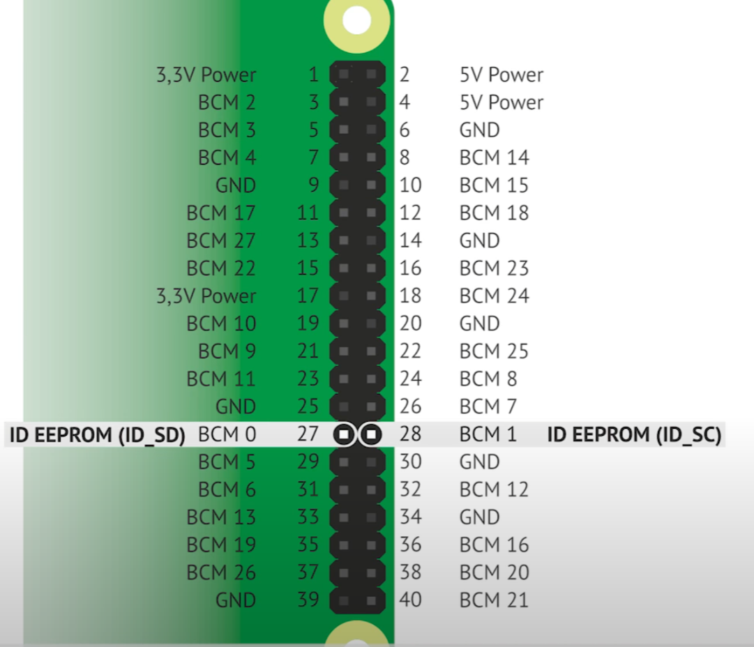
Распиновка
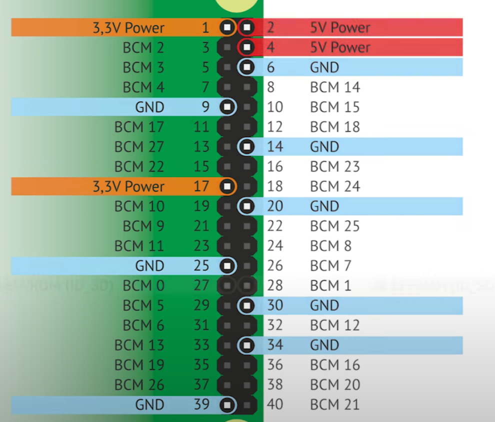
Зарезервированно под HAT Devices(Hardware attached on top), то есть обычные шилды
То что можно использовать для подключения к GPIO
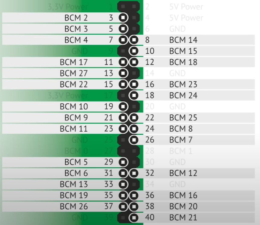
Различные ресурсы
https://pinout.xyz/pinout/ground